Understanding Voltage, Current, and Power for Electronics Projects
Confused by 5V, 2A, watts, adapters, batteries, and power ratings? This practical guide explains voltage, current, and power in simple terms, with real examples for Arduino, Raspberry Pi, LEDs, motors, sensors, and everyday electronics projects.
A practical guide for real-world electronics projects
When you are building electronics, three words keep appearing everywhere: voltage, current, and power.
They show up on power adapters, batteries, development boards, motors, LEDs, relays, sensors, and product pages. You will see ratings like 5V 2A, 12V 1A, 3.3V logic, 10W, 250mA, or 24V DC.
At first, these numbers can feel like a secret language printed on tiny labels. But once you understand what they mean, electronics becomes much easier, safer, and less mysterious.
This guide explains voltage, current, and power in a practical way, with examples you will actually use in projects.
The quick idea
Think of an electronic circuit as a system that needs electrical energy to do something useful.
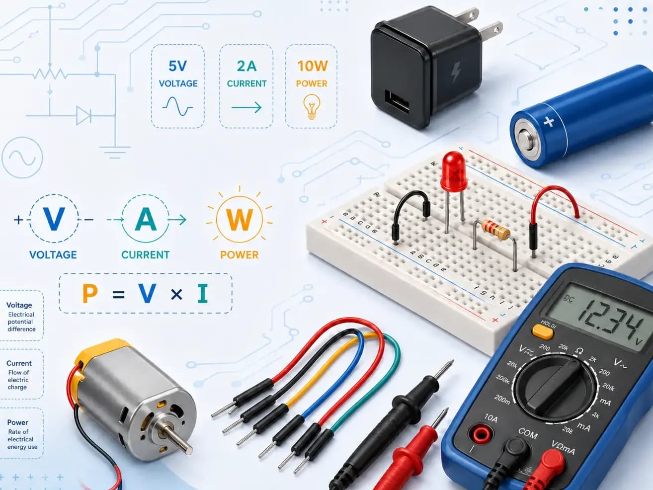
Voltage is the electrical pressure that pushes energy through a circuit.
Current is the amount of electric charge flowing through the circuit.
Power is how much electrical energy is being used or delivered per second.
The relationship between them is:
Power = Voltage × Current
P = V × I
Where:
P is power in watts, W
V is voltage in volts, V
I is current in amperes, A
So if a device uses 5V and draws 2A, its power use is:
5V × 2A = 10W
That device needs a power supply capable of delivering at least 10 watts.
Voltage: the electrical pressure
Voltage is measured in volts, written as V.
In real projects, voltage is usually the first thing you must match correctly. If your board needs 5V, give it 5V. If a sensor needs 3.3V, do not connect it directly to 5V unless the sensor is specifically rated for it.
Common voltages in maker projects
VoltageWhere you commonly see it1.5VAA/AAA cells3.3VESP32, Raspberry Pi GPIO, many sensors3.7VSingle-cell Li-ion or LiPo battery nominal voltage5VArduino boards, USB power, Raspberry Pi power input, modules9VSome beginner kits, older battery-powered circuits12VMotors, LED strips, relays, pumps, fans24VIndustrial sensors, CNC, 3D printers, automation systemsWhy voltage matters
Voltage must usually be matched to the device.
A 5V Arduino should not be powered from 12V directly into the 5V pin. A 3.3V sensor may get permanently damaged if connected to a 5V signal. A 12V motor may not run properly at 5V, or may run weakly.
Too little voltage can cause unstable behavior. Too much voltage can cause heat, smoke, or permanent damage.
Electronics is polite until voltage is rude.
Current: how much flow the device takes
Current is measured in amperes, written as A. Smaller currents are often written in milliamps, or mA.
1A = 1000mA
0.5A = 500mA
0.05A = 50mA
A very important idea:
A device draws the current it needs, as long as the power supply can provide it.
This means a 5V 3A power adapter does not force 3A into your device. It simply means it can provide up to 3A safely.
For example, if a small sensor needs 50mA, you can power it from a 5V 2A supply. The sensor will still take only around 50mA.
Current rating of a power supply
The current rating on a power supply is its capacity.
Device requirementSuitable power supply?Why5V 500mA5V 1AYes, enough current capacity5V 500mA5V 3AYes, more capacity is fine5V 2A5V 1ANo, supply may overheat, shut down, or voltage may drop12V 1A5V 2ANo, wrong voltage5V 1A12V 1ANo, voltage too highThe voltage should match. The current capacity should be equal or higher.
Power: how much work the circuit is doing
Power is measured in watts, written as W.
Power tells you how much energy a device uses per second. A tiny sensor may use a fraction of a watt. A motor, heater, LED strip, or 3D printer can use much more.
The formula is:
Power = Voltage × Current
Example 1: Raspberry Pi power
A Raspberry Pi powered by 5V and drawing 2.5A uses:
5V × 2.5A = 12.5W
So a weak phone charger rated at 5V 1A is not enough. The Pi may show undervoltage warnings, reboot, or behave unpredictably.
Example 2: 12V LED strip
A 12V LED strip draws 2A.
12V × 2A = 24W
You should use a 12V supply rated above 2A, preferably with some margin. A 12V 3A or 12V 5A supply would be more comfortable than a supply running at its limit.
Example 3: Small DC motor
A motor is rated 12V 500mA while running normally.
12V × 0.5A = 6W
But motors often draw much more current when starting or when stalled. A motor that normally uses 500mA may briefly draw 1A, 2A, or more. This is why motor power supplies need extra headroom.
The most useful formula in electronics
You will use this constantly:
P = V × I
You can rearrange it too:
I = P ÷ V
V = P ÷ I
Example: How much current does a 10W device need at 5V?
I = P ÷ V
I = 10W ÷ 5V
I = 2A
So a 10W device running at 5V needs 2A.
Example: How much current does a 10W device need at 12V?
I = 10W ÷ 12V
I = 0.83A
The same power at a higher voltage needs less current.
This is one reason higher-voltage systems are common in LED strips, 3D printers, CNC machines, and automation systems. Less current means thinner wires can often be used, and there is usually less voltage drop over long cables.
Voltage vs current: what damages components?
Both can matter, but in different ways.
Too much voltage
Too much voltage can punch through delicate parts inside a component.
Examples:
Connecting a 3.3V sensor to 5V logic
Powering a 5V board from 12V incorrectly
Using the wrong adapter for a module
Reversing polarity on a DC input
Damage can be instant.
Too much current
Current becomes dangerous when a circuit allows more flow than the parts can safely handle.
Examples:
LED connected without a resistor
Thin jumper wires used for a large motor
Motor driver overloaded
Short circuit between power and ground
Relay contacts used beyond their rating
Too much current usually creates heat. Heat creates smell. Smell creates regret.
Important concept: current is drawn, not pushed
A common beginner fear is:
“My board needs 5V 1A. Can I use a 5V 3A adapter, or will it burn the board?”
Yes, you can use it, as long as the voltage is correct and polarity matches.
The board will draw what it needs. The adapter’s current rating is just the maximum it can safely provide.
A good analogy is a water tap with a large tank behind it. A larger tank does not force all the water out at once. The circuit opens the tap as much as it needs.
But there is one warning: if there is a short circuit or faulty wiring, a high-current supply can deliver a lot of current into the fault. That is why fuses, current-limited supplies, and careful wiring are important in larger projects.
Real-world example: powering an Arduino with sensors and a relay
Suppose you are building a small automation project:
Arduino Uno: around 50mA to 100mA
16x2 LCD: around 20mA to 100mA depending on backlight
Temperature sensor: around 1mA to 5mA
Relay module: around 70mA to 90mA
Buzzer: around 30mA
Estimated total:
100mA + 100mA + 5mA + 90mA + 30mA = 325mA
A 5V 500mA supply might work, but it has little margin. A 5V 1A supply is a better choice.
In electronics, do not design the power supply like a suitcase that barely closes. Leave room.
Real-world example: Raspberry Pi with USB devices
A Raspberry Pi may run from 5V, but the current depends on what is connected.
A Pi alone may work with modest current, but add:
USB keyboard
USB camera
SSD
HAT module
Cooling fan
Now the current requirement increases.
If the power supply is weak, you may see:
Random reboots
SD card corruption
USB devices disconnecting
Wi-Fi instability
Undervoltage warnings
Many “software bugs” in Raspberry Pi projects are actually power problems wearing a fake moustache.
Real-world example: motors need special treatment
Motors are not like sensors. They are hungry, noisy, and dramatic.
A small DC motor may say 6V 300mA, but that is often the running current under light load. During startup, heavy load, or stall, the current can be several times higher.
For motors:
Use a proper motor driver.
Do not power motors directly from microcontroller pins.
Use a separate supply if needed.
Make sure grounds are connected when using separate supplies.
Add flyback protection for coils, relays, and inductive loads.
Choose a supply with extra current capacity.
A microcontroller pin can usually provide only a small current. A motor can demand much more. Connecting a motor directly to a GPIO pin is a fast way to turn a smart board into a tiny paperweight.
Real-world example: LEDs and resistors
LEDs are current-sensitive components. They need current limiting.
A bare LED should not be connected directly across a battery or power supply unless the LED module already includes a resistor or driver.
For a simple LED circuit, you usually need a resistor in series.
Example:
Supply voltage: 5V
Red LED forward voltage: about 2V
Desired current: 10mA
Voltage across resistor:
5V - 2V = 3V
Using Ohm’s law:
R = V ÷ I
R = 3V ÷ 0.01A
R = 300Ω
A common nearby value is 330Ω.
Without a resistor, the LED may draw too much current and fail.
What is voltage drop?
Voltage drop means some voltage is lost across wires, connectors, switches, or components because they have resistance.
This becomes important when:
Current is high
Wires are long
Wires are thin
Connectors are poor quality
Motors or LED strips are used
For example, a 5V device at the end of a long thin cable may receive only 4.6V or 4.7V when under load. That can be enough to cause problems.
This is common with Raspberry Pi boards, LED strips, servo motors, and USB-powered projects.
How to reduce voltage drop
Use shorter wires.
Use thicker wires.
Use better connectors.
Use a higher-voltage supply with a buck converter near the device.
Inject power at multiple points for long LED strips.
Avoid powering high-current loads through breadboards.
Why breadboards are not for high current
Breadboards are excellent for learning and small prototypes. They are not designed for high-current loads.
Use breadboards for:
Sensors
Logic circuits
Small LEDs
Microcontroller signals
Low-current experiments
Avoid breadboards for:
Motors
Heaters
Long LED strips
High-current relays
Power-hungry modules
Breadboard contacts are small. High current can cause poor connections, voltage drop, heat, and unreliable behavior.
For bigger loads, use screw terminals, proper wiring, soldered connections, terminal blocks, or PCBs.
AC vs DC: check before connecting
Most electronics projects use DC, or direct current. Batteries, USB supplies, Arduino boards, Raspberry Pi boards, and most modules use DC.
Wall power is AC, or alternating current.
A power adapter converts AC from the wall into DC for your project.
Always check the label:
Output: 5V DC 2A
Output: 12V DC 1A
Do not connect AC directly to DC electronics.
Also check polarity. Many barrel jack adapters are center positive, but not all devices are the same.
Regulators, buck converters, and boost converters
Sometimes your available voltage does not match what your circuit needs. That is where voltage converters come in.
Linear regulators
A linear regulator reduces voltage, for example from 9V to 5V.
They are simple but can waste extra energy as heat.
Example:
A 9V input is regulated down to 5V at 500mA.
The regulator must drop:
9V - 5V = 4V
Heat wasted:
4V × 0.5A = 2W
2W of heat is a lot for a small regulator without cooling.
Buck converters
A buck converter efficiently steps voltage down.
Examples:
12V to 5V
24V to 12V
7.4V battery to 5V
Buck converters are better for higher current projects.
Boost converters
A boost converter steps voltage up.
Examples:
3.7V battery to 5V
5V to 12V
Boost converters are useful, but remember that increasing voltage usually means drawing more current from the input side.
There is no free lunch in power electronics. The lunch has a switching frequency.
Battery capacity: mAh is not the full story
Batteries are often rated in mAh, or milliamp-hours.
Example: a 2000mAh battery can theoretically provide:
2000mA for 1 hour
1000mA for 2 hours
500mA for 4 hours
But real battery life depends on:
Battery voltage
Load current
Converter efficiency
Battery age
Temperature
Discharge limits
Current spikes
To compare energy properly, use watt-hours:
Wh = V × Ah
A 3.7V 2000mAh Li-ion cell has:
3.7V × 2Ah = 7.4Wh
If your project consumes 5W, ideal runtime is:
7.4Wh ÷ 5W = 1.48 hours
In reality, after converter losses, it may be closer to 1 to 1.3 hours.
Choosing a power supply for your project
Use this simple process.
Step 1: Find the required voltage
Check every device:
Microcontroller board
Sensors
Motors
Relays
LED strips
Displays
Communication modules
Make sure each part gets the voltage it expects.
Step 2: Estimate current
Add up the current requirements of all parts.
Example:
PartCurrentMicrocontroller100mADisplay150mASensor modules50mARelay module80mAFan300mATotal680mAStep 3: Add margin
Do not choose a supply that barely matches the total.
For a 680mA project, choose at least 1A. If there are motors, pumps, servos, GSM modules, or LED strips, add more margin.
Step 4: Check connector and polarity
Voltage and current may be correct, but the connector may still be wrong.
Check:
Barrel jack size
USB-C, micro-USB, screw terminal, JST, etc.
Center-positive or center-negative polarity
Wire thickness
Terminal rating
Step 5: Test under real load
Measure the voltage while the project is running, not only when idle.
A supply may show 5V with no load, but drop under load. That drop can cause resets and random failures.
Common mistakes and how to avoid them
Mistake 1: Correct current, wrong voltage
A 12V 2A adapter is not suitable for a 5V 2A device.
The current rating is not enough. Voltage must match.
Mistake 2: Powering motors from microcontroller pins
GPIO pins are for signals, not motor power.
Use a transistor, MOSFET, relay, or motor driver depending on the load.
Mistake 3: Forgetting common ground
If you use separate supplies, such as one for a motor and one for a microcontroller, their grounds often need to be connected together so control signals have a shared reference.
Mistake 4: Ignoring startup current
Motors, pumps, solenoids, relays, GSM modules, and large capacitive loads may draw current spikes.
Choose a supply that can handle these peaks.
Mistake 5: Using thin wires for high current
Thin wires can heat up and cause voltage drop.
Use appropriate wire thickness for motors, heaters, LED strips, and batteries.
Mistake 6: Assuming USB means enough power
USB voltage may be 5V, but current depends on the port, cable, adapter, and negotiation. Some cables are power-starved noodles in disguise.
Measuring voltage and current with a multimeter
A multimeter is one of the most useful tools for electronics.
Measuring voltage
To measure voltage:
Set the multimeter to DC voltage.
Place the black probe on ground or negative.
Place the red probe on the point you want to measure.
Measure across two points in parallel.
Voltage is measured across a component or supply.
Measuring current
To measure current:
Set the multimeter to current mode.
Move the red probe to the current input socket if needed.
Break the circuit.
Insert the meter in series with the load.
Current is measured through a circuit path.
Be careful. Measuring current incorrectly can short the supply through the meter.
For higher current projects, a USB power meter, clamp meter, or bench power supply with current display can be very helpful.
Quick reference table
TermUnitSymbolWhat it meansVoltageVoltVElectrical pressureCurrentAmpereAFlow of electric chargePowerWattWEnergy used per secondResistanceOhmΩOpposition to current flowCapacityAmp-hourAh / mAhBattery charge capacityEnergyWatt-hourWhTotal stored or used energyPractical checklist before powering a project
Before connecting power, ask:
What voltage does each part need?
Is the supply DC or AC?
Is the polarity correct?
Can the supply provide enough current?
Have I added margin for startup current?
Are my wires thick enough?
Are high-current loads kept off the breadboard?
Do separate supplies share ground where needed?
Is there a fuse or protection for larger projects?
Did I test the voltage under load?
This checklist can save boards, batteries, sensors, and weekends.
Final takeaway
Voltage, current, and power are the foundation of every electronics project.
The most important rules are:
Match the voltage.
Use a power supply with enough current capacity.
Calculate power with P = V × I.
Add margin for real-world behavior.
Be extra careful with motors, batteries, heaters, and LED strips.
Measure under load when troubleshooting.
Once these ideas click, you will stop guessing and start designing power systems with confidence.
Electronics becomes much friendlier when the invisible numbers have names.